create levels from Excel part 2 (Dynamo to C#) link
May 21, 2021
 Happy Friday! This week we are finishing our plug-in that will read an excel file and create levels from the excel file. We are taking the common Dynamo script as a guide and walking through how you would write this in C#. The goal is to show how Dynamo nodes and script structure relates to the Revit API so you can relate the two as you start coding.
Last week
, we read the excel file so this week we just need to set up our method to create the levels and execute our program.
Happy Friday! This week we are finishing our plug-in that will read an excel file and create levels from the excel file. We are taking the common Dynamo script as a guide and walking through how you would write this in C#. The goal is to show how Dynamo nodes and script structure relates to the Revit API so you can relate the two as you start coding.
Last week
, we read the excel file so this week we just need to set up our method to create the levels and execute our program.
Dynamo script
I am using a simple script that many people have made versions of for creating floor levels in Revit from an Excel spreadsheet. The script is roughly based on one of the scripts from ArchSmarter's article Save Time with Revit Dynamo.

The script has 3 basic parts:
- Determine the Excel file’s path and read the file
- Clean up the information from the file
- Create the levels and adjust the name of the levels
create levels
The last part of our Dynamo script is creating the levels. In order to do that in our program, we can review the methods available in the Level class in the Revit API documentation. We see that we can use the Create method. So we can write our method which will not return anything. It will need the document and our two lists with the level names and heights that we modified last week as parameters. Then we can create a for-loop with a counter to go through each item in our list. The Create method requires the height to be a double and currently our level heights are stored as strings so we will need to parse our value to a double. Please also note that the Revit API create levels with decimal feet so you would need to add a conversion if your excel file lists the height in meters. This information can be found in the API documentation. Then we can use Level.Create to create our level. Finally, we can rename the level with the name from our list.
execute
The last step for our program does not directly relate to our Dynamo script but it is the most important step to have our application run. We need to write our execute method. First we will declare our variables. We always want to have our active document and document since we use these for almost every method in the Revit API. Then we also want to have a variable for the application for debugging. After that, we can move on to the variables specific to our program. We will need the file location for the Excel file which you will need to enter and the name of the sheet which you will need to update if you renamed it. Finally, we want two empty lists. One will store the level names, and one will store the level heights. These are the lists we have used in our methods so far to store the data from excel.
Then we can call our methods. We will want to put this in a try catch loop so our program reports the error if it fails. Additionally, When making changes to the Revit document, you need to wrap your changes in a transaction. This is in order to allow you to roll back changes if your code fails part way through. Revit won’t allow you to make changes outside of a transaction, so we put our CreateLevels method in one.
wrapping it up
As is noted in Autodesk's My First Revit Plugin we also need a Ribbon class and an .addin file to run our program. The ribbon class puts your plug-in button on the Revit ribbon and you will need to provide an icon. You can review these pieces for this program on my GitHub page. You will need to update the Excel file path as noted above and compile it to use it.
summary
And that’s how we can translate a Dynamo script into a basic plug-in. You can expand on your plug-in by adding a UI with WPF which would allow users to enter their own file path instead of hard-coding it. This would also allow you to add other options and features if you wanted to expand on the program. There’s lots of options once you have a foundation for your plug-in. Happy coding!
create levels from Excel part 1 (Dynamo to C#) link
May 14, 2021
 Happy Friday! A few weeks turned into a few months, but I’m so grateful I was able to take some time to focus on my watercolor class and keep painting for a bit after. It was so wonderful to see some familiar faces I hadn’t seen in a while and meet so many talented artists. I’m back to blogging and writing some code, but want to keep painting too so I’ll have a slightly adjusted schedule for posting.
This week I’m kicking things off again by taking a common Dynamo script (creating levels from an Excel spreadsheet) and walking through how you can write a Revit Plug-In in C# to complete this same task. The goal is to show how Dynamo nodes relate to coding and the Revit API.
If you haven't built a Revit plug-in yet, I would recomend working through Autodesk's
My First Revit Plugin to familiarize yourself with the process and setting up a new project in Visual Studio.
Dynamo script
I am using a simple script that many people have made versions of for creating floor levels in Revit from an Excel spreadsheet. The script is roughly based on one of the scripts from ArchSmarter's article Save Time with Revit Dynamo.

The script has 3 basic parts:
- Determine the Excel file’s path and read the file
- Clean up the information from the file
- Create the levels and adjust the name of the levels
Excel file
In order to read an Excel file, you will need to have Excel installed on the machine you are writing your code on. You will also need to install and import the Microsoft Office Interop Excel Services using the Microsoft.Office.Interop.Excel NuGet package. I assigned it to a variable to make using it easier which I will show next week when I post all the code.
The first method we are going to write reads the Excel file and stores the data in lists. Our method won’t return anything but we will need the file location and sheet name as parameters. Additionally we will want one parameter for the level names and one for the level heights. All these parameters will be declared in our execute method which we will cover next week.
In order to launch Excel and read the file, we need to instantiate a new Excel application. This is the object which allows us to manage our Excel connection. Then, we open the file, read the sheet, and assign all cells with values to a new Excel Range object. We can then cycle over the data in the Excel Range object just as we would a list in Dynamo. The Excel Range has a Rows property which we can use to get the number of rows it has. This will tell us the total number of levels we are creating but will also include headers.
In order to get the information in the first column, we can set up a for-loop with a counter. Note that Excel Ranges are not zero indexed so we will want to use 1 to get the first row, 2 for the second, and so on. In this case, we can also assume our Excel file has headers and skip the first row so we will start at index 2. We first want to check if our cell has a value by using string.IsNullOrEmpty. If it has a value, we want to take that value and add it to our list of level names. We do the same thing for the second column but add it out our level heights list.
Then we need to complete some memory management and quit Excel. First, we deallocate memory, release the communications object to kill the Excel process that is running in the background, close and release the workbook, and finally, quit and release the application.
Summary
And that is how we can read an Excel file using code based on the first two parts of our Dynamo script. As you can see, some processes are simpler to execute like removing the header by starting at index 2 instead of 1 in our for loop. Others are more complex like opening the Excel file, managing memory, and keeping track of variables and outputs. Next week, I will dive into the Revit API and cover how to create levels as well as how to set up the execute method.
gone painting link
February 5, 2021
Happy Friday! I had an excellent oppertunity to enroll in an online watercolor class
taught by one of my previous professors from Cal Poly and decided to take the time to develop one
of my other passions - watercolor. I will be focusing on the class and some of my other projects
so I won't be posting this month.
If you are looking for a great learning oppertunity,
learn Python with Ehsan and Dana on YourDesk University.
The workshop is free, but
sign-up is required.

webhook node (to track ROI) link
January 22, 2021
 Happy Friday! When you are trying to track ROI, you need data. One easy way to
start gathering usage and ROI data is to set up a webhook with an application like Slack.
The process is very similar to how we integrated a
webhook in our plug-ins.
If you haven’t used webhooks with Slack,
check out their documentation.
Happy Friday! When you are trying to track ROI, you need data. One easy way to
start gathering usage and ROI data is to set up a webhook with an application like Slack.
The process is very similar to how we integrated a
webhook in our plug-ins.
If you haven’t used webhooks with Slack,
check out their documentation.
inputs
We will have four inputs to the node: the name of the script, the telemetry URL, ROI information (in minutes), and an additional message. The telemetry URL will come from your Slack application and can be copied and pasted into a string node in Dynamo. When the script is run, we send a number of messages to Slack via the webhook. First we send the message that we started, then we take care of some formatting.
ROI message and user data
We reformat the ROI input from minutes to hours so we can compile it into one concise statement. Then we can concatenate the string to add the text entered in the message input.
There are a few pieces of additional information we want to collect: the username of the person running the script and the current date and time. We also declare our variable for the formatted message so we can combine all this information. Our formattedMessage will start by listing the name of the script (from the node input) and then the username and current date and time we just collected. We can then add our ROI message after. If there is other data you want to collect, you can customize the inputs and information to send additional data.
Now that we have our message with all the information we want to collect, we can
create a StringContent object so that the library can correctly send our message.
We pass through the message string, our string encoding (UTF8), and the data format
(application/json). Then we can send it to our webhook URL. It will
then post to the Slack channel that we have set up with our application.
For our node, we want to return the message as a string so we know it ran successfully.

summary
When you need to collect some basic information on Dynamo script usage, you can use a node that sends data via webhook to an application like Slack. It is a fast and easy way to start tracking script usage and to collect ROI information.
Disclaimer: This post is intended to explain how to collect data relevant to tracking and understanding ROI. Please review any relevant privacy and protection policies before collecting data.
All products mentioned are used as examples for educational purposes only. Always confirm an application’s Terms of Use.
resources
If you want to learn to code and don’t know where to start check out my posts about Steps to Learn to Code [for architects and designers] Part 1 and Part 2.
custom dropdown menu (part 2) link
January 15, 2021
 Happy Friday! Last week, we set up our project to write a Zero Touch Node for Dynamo
so that this week, we can start creating some custom dropdown nodes. I did update
last week's
post to include two additional DLL files you will need to reference: ProtoCore.dll and NewtonSoft.Json.dll.
For this
example, I will walk through two different dropdown menus. They both use
FilteredElementCollectors to get the elements we need for our menu. You can of
course completely customize the nodes to fit your needs.
Happy Friday! Last week, we set up our project to write a Zero Touch Node for Dynamo
so that this week, we can start creating some custom dropdown nodes. I did update
last week's
post to include two additional DLL files you will need to reference: ProtoCore.dll and NewtonSoft.Json.dll.
For this
example, I will walk through two different dropdown menus. They both use
FilteredElementCollectors to get the elements we need for our menu. You can of
course completely customize the nodes to fit your needs.
area plans
The first node we want to put together is a dropdown that only displays the different area plans in the project. We can create our class and call it AreaPlans. We want to add the attributes we discussed last week so that it is easier to control how everything is labeled in Dynamo.
First, we need to write our constructor. Then, we can use the PopulateItemsCore method, however we want to override it’s functionality so that we can populate it with our own items. The method we are overriding is protected, so our method will also be protected, it will return a SelectionState and the method name stays the same.
To use a filtered element collector, we need the active document, which we can assign to a variable called doc. Using Revit LookUp we can see that Area Plans are ViewPlans where the ViewType is AreaPlan. This allows us to easily set up a filtered element collector for our AreaPlans.
After we collect all of our area plans, if no elements were collected, we want to return null with the message “No area plans” available. If elements were collected, we want to sort them based on the Title property. This allows them to appear in alphabetical order by Title in our drop down. We also need to return our SelectionState.
Then we need to build our output. We are going to override the BuildOutputAst method. If it does not have an Area Plan to output, we want to return null. Otherwise, it will select the Area Plan from the drop down and return the ElementId as an integer.

title blocks
To create a dropdown just for title blocks works almost exactly the same way. We want to create a new class and can update the attributes. Since we want to specifically get all the types of title blocks in the project, not a list of the placed title blocks, we want to look for FamilySymbol not FamilyInstance. Title block families have “Title Blocks” as the name of their Category parameter so we can use this to filter for all the required families. This time, we want to sort by the element’s name and also use the name to display in the dropdown list, but return the title block family element.
summary
And in just a few simple steps, we can create a large variety of custom dropdown nodes to use in Dynamo. This can help to simplify selections in your scripts and make them faster and easier to use. Don’t forget, the DLL for your custom nodes will need to be located on the computer of everyone who needs to use the script, just like packages. Happy customizing!
resources
If you want to learn to code and don’t know where to start check out my posts about Steps to Learn to Code [for architects and designers] Part 1 and Part 2.
custom dropdown menu (part 1) link
January 08, 2021
 Happy Friday and Happy New Year! I hope you all enjoyed the holidays and found some time to relax. We filled our days with puzzles, boardgames, and walks which was a great way to unwind. I knew there would come a time when the packages for Dynamo wouldn’t have exactly the tools I needed and I would dive into the work of custom dynamo nodes. Currently, I have a few scripts that I would like to make more user-friendly by filtering the dropdown menu to very specific items. As I was trying to put together a custom dropdown menu, I spent a lot of time looking through existing resources and although all the information is out there, I thought I would compile everything in one place to make it easier to reference.
zero touch nodes
Zero Touch Nodes (ZTN) are custom Dynamo nodes that are written in C#, compiled, and then used inside Dynamo by importing the DLL. If you have never created a Zero Touch Node, I would recommend Thomas Mahon’s excellent course “Become a Dynamo Zero Touch C# Node Developer in 75 Minutes”. It clearly walks through how to set up your project in Visual Studio and how to create your first node as well as covering some C# basics, dynamo node development basics, and more. This walkthrough did not have information on all the references we need to import into our project because they weren’t required for the tutorial, but we do need some for the node we are making so I will review these later in this post.
node naming - using attributes
As Thomas explains, public methods appear as Dynamo nodes. Node naming is taken from the DLL, namespace, and class names which can be inconvenient. One helpful piece of information I learned through this process is that you can use attributes, some people refer to them as class decorators, which allow you to override the node name, category, description, and other information so that Dynamo doesn’t pull the naming from the DLL, namespace and class names Thomas describes. Based on the information I found, you can only use the attributes on a class so each node you create will need to be a new class. You will need some of the references mentioned below to use them.
required references
Konrad Sobon posted excellent information in response to a question on the Dynamo forum that got me on the right track for creating a custom dropdown node. We will be using the RevitDropDownBase class that Konrad mentioned to create our menu. First though, we need to track down and import the following references into our C# project. I was working with Revit 2019 but these should also be available in the later Dynamo and Revit folders.
- C:\Program Files\Autodesk\Revit 2021\AddIns\DynamoForRevit\nodes\CoreNodeModels.dll
- C:\Program Files\Autodesk\Revit 2021\AddIns\DynamoForRevit\Revit\nodes\DSRevitNodesUI.dll
- C:\Program Files\Autodesk\Revit 2021\AddIns\DynamoForRevit\DynamoCore.dll
- C:\Program Files\Autodesk\Revit 2021\RevitAPI.dll
- C:\Program Files\Autodesk\Revit 2021\AddIns\DynamoForRevit\Revit\RevitServices.dll
- C:\Program Files\Autodesk\Revit 2021\AddIns\DynamoForRevit\ProtoCore.dll
- C:\Program Files\Autodesk\Revit 2021\NewtonSoft.Json.dll
summary
These are all the references we need in order to use the RevitDropDownBase class and others along with the attributes. Now that we have set up our project and imported the required references, we can create our custom node, which I will walk through next week.
resources
If you want to learn to code and don’t know where to start check out my posts about Steps to Learn to Code [for architects and designers] Part 1 and Part 2.
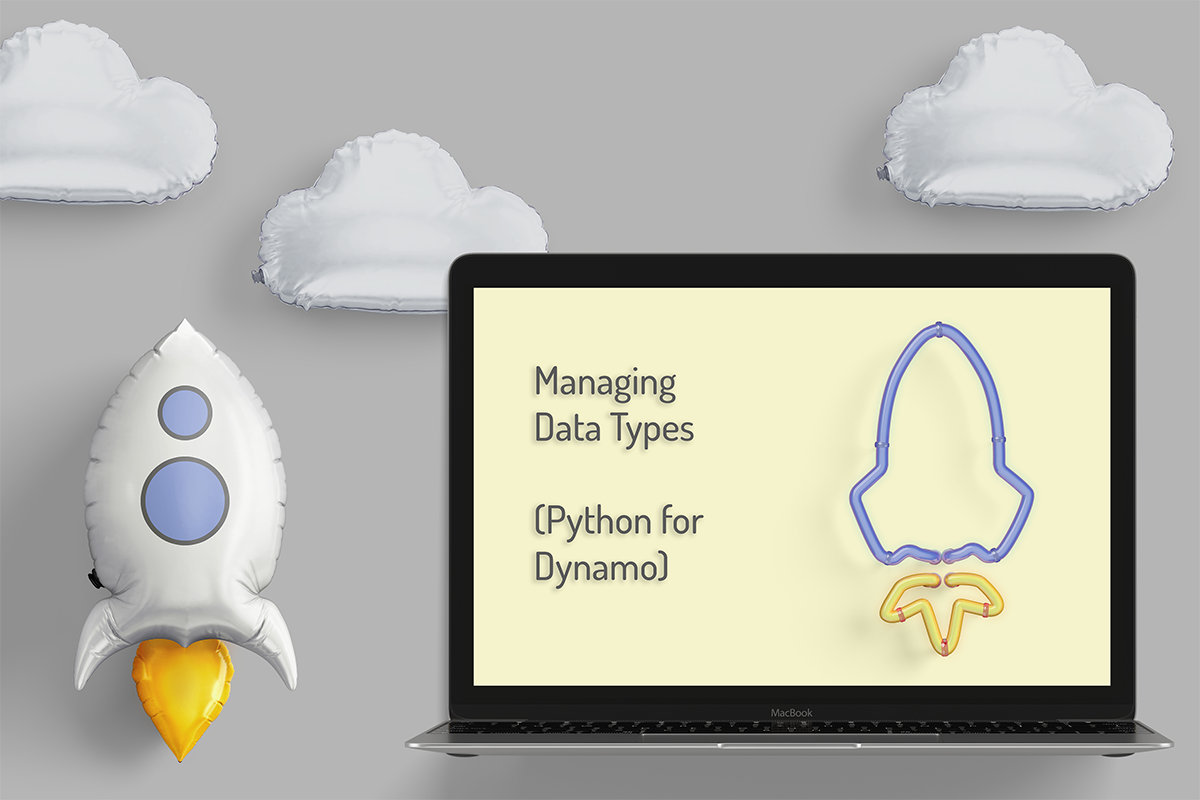
managing data types (python for Dynamo) link
December 18, 2020
 Happy Friday! I hope you all enjoyed AU this year and had a great time during the recent holidays. I know for my husband and I, it was nice to have a very small gathering with just our immediate family for Thanksgiving. We also got to do a lot of hiking, which we loved! I can’t believe it’s all gone by so fast and we are now past mid-December.
If you want to start learning how to code, python is a popular choice with a wide variety of applications. For example, you can use it for custom nodes in Dynamo. A great stepping stone is to start turning pieces of your graph into python nodes. I frequently do this with filtering as mentioned in a previous post, especially for parameters, because it speeds up the process. It can also be used to efficiently get the data type you need.
data types
I noticed there were a couple tasks that I always use Python nodes for and I decided to share another one. For this graph, I am taking the phase created and phase demolished parameters and copying the name of the phase as a string into a custom parameter. I need to write this phase as text to a text parameter so I can use it for a filter in a view template.
I find that I frequently need to change and manage the data type of outputs from various Dynamo nodes. For example, when you get the phase of an element using the Element.Phases node, it returns an object representing the phase element. In order to copy this to a string, we need the name, but we also need to handle the cases for when the phase is none. To accomplish this, we can add a couple lines of code in a python node.
Our IN will be a list of the phases. In this case, phase demolished. We will also need a new empty list to store the text in. Then we look at each phase in the phaseDemolished list. If it is equal to none, we add the text “none” to our phaseDemolishedText list. Otherwise, we get the name of the phase as a string and put that into our list. Then we can output our phaseDemolishedText list and the node will return a list of strings noting either the phase name or “none” based on the conditions.
Then we can use that in our graph to copy both the Phase Created and Phase Demolished parameters to a text parameter. And this is what the graph looks like in use:

summary
Thank you for all the support this year. I can say it has certainly been strange. There are so many things that have not gone right, but there are also things I am grateful for, like getting to spend more time with my family. I will not be posting over the next two weeks, but will be back to a more regular schedule in January. I wish you happy holidays and all the best for the new year.
resources
If you want to learn to code and don’t know where to start check out my posts about Steps to Learn to Code [for architects and designers] Part 1 and Part 2.
Export OBJ Using C# link
With guest writer: Andreas Brake
December 11, 2020
 Happy Friday! This week I am excited to welcome back
Andreas Brake
as the guest writer for
this post. He is a software engineer at Topgolf Media doing server development. In his free time,
he enjoys hiking, gaming, and gardening. This week, he will discuss how to export Revit geometry
as OBJ files using C#, a feature we used when working on
StreamVR,
a Hackathon project we did in August.
Happy Friday! This week I am excited to welcome back
Andreas Brake
as the guest writer for
this post. He is a software engineer at Topgolf Media doing server development. In his free time,
he enjoys hiking, gaming, and gardening. This week, he will discuss how to export Revit geometry
as OBJ files using C#, a feature we used when working on
StreamVR,
a Hackathon project we did in August.
motivation
One exciting usage of Revit plugins is to add interoperability between Revit and external programs. This can take many forms, but sometimes you may want to transfer geometry from Revit including Families in the model. This presents some difficulty, as Revit allows exporting Families as FBX files or other proprietary formats but lacks a built-in export to a widely used open format such as OBJ. This post will be describing what an OBJ model looks like and how to create one in C# using the Revit API.
what is an .obj file
Simply put, an OBJ file is a plain-text file that contains structured information that describes some arbitrary geometry. In its most basic form, this file will define a series of vertices and faces that can be read and reconstructed into a 3D model. The example below defines a Cube.
Click Here to download this example OBJ. This download is generated in-browser so no data will be sent to any server.
In addition to these simple parameters, an OBJ file can be extended with information for applying correct normal vectors and texture mapping among many other features. This post will consider the more basic features for brevity, but further examples of OBJ files can be found here.
Beyond geometry information, an OBJ file can also contain organizational lines that allow for sub-geometry to be defined. These organizational groups can also be given names that can be read by external model editors.
Because an OBJ file only contains plain-text information, it becomes a good option for interoperability as it is then easier to serialize and transmit as a file, over HTTP, or really any other channel for communication between programs.
code overview
Our code starts by assuming that the program has access to the current Document and an ElementId for a FamilySymbol. To review: a "Family" that is placed in a Revit Model is represented in code as a FamilyInstance object which contains positional, rotational, and other instance data. This object is a child of a FamilySymbol object. A FamilySymbol defines the Geometry for a "Family" and is a shared parent for all FamilyInstances of the same type. Beyond this, there exists a true Family object that is the parent of one or more FamilySymbols and can act as a container for variations of similar FamilySymbols. This post will only focus on and interact with FamilySymbols.
The high-level structure of our function looks like this:
Here, we get the FamilySymbol and iterate over each GeometryObject associated with it. GeometryObjects can represents various types of 1D, 2D, and 3D forms, but we will consider only Solids. We start our OBJ file data by creating a StringBuilder which will help us build out longer strings than would be reasonable using simple string concatenation. This StringBuilder will then have appended to it our first line of the file. This is an "o <name>" line that tells any reading program that the following lines will contain geometry for the <name> object.
For each Solid, we will write a "g <name>" line that will tell the reader to consider each face as a separate grouping. This is technically optional, but can help for model organization.
We then get and process each Face that is part of the Sold. For each Face, we can use the helpful Triangulate method exposed by the Revit API:
This block is where we actually write the bulk of our file’s contents. First, we iterate over the Vertices member of the Face's Mesh and write each of these to the file as a "v <x> <y> <z>" line. Note that sometimes, you may have to swap the Y and Z coordinates to orient the output model correctly.
After we have the vertices, we generate the triangles that will define our geometry. Luckily for us, Revit exposes some nice methods to help with getting these triangles. We can first iterate over the total number of triangles in the mesh and process each one individually. In order to create a "f <v1> <v2> <v3>" line, we need the indexes of the vertices as they appear in the OBJ file. This means that we have to keep track of the global vertex index using an "indexOffset" variable. Between this and the index, as retrieved from the MeshTriangle, we can compute a global index value for the desired triangle vertex and write these to the file.
Finally, we increment our various counters to track offsets and face numbers across face and part iterations.
After we have our full StringBuilder object, we can write this OBJ to a file like so:
We are writing to the system’s Temp path for ease of access, but an actual destination is up to you as the coder. Because the OBJ is simply a string, there are other options than writing to a file. It could also just as easily be sent over HTTP to a remote server or used elsewhere in the program.
resources
If you want to learn to code and don’t know where to start check out my posts about Steps to Learn to Code [for architects and designers] Part 1 and Part 2.
place material tag link
November 20, 2020
 Happy Friday! I took a break last week because my husband and I took a road trip
for a few days. It was great to get a break and relax. We had the chance
to do some hiking in Zion which was beautiful! We even got some snow. Today,
we’re back with the last post of the series. This will be the last plug-in for
the year but I have some great content for the rest of the year including another
guest post about exporting OBJ from Revit and some Dynamo scripts.
Happy Friday! I took a break last week because my husband and I took a road trip
for a few days. It was great to get a break and relax. We had the chance
to do some hiking in Zion which was beautiful! We even got some snow. Today,
we’re back with the last post of the series. This will be the last plug-in for
the year but I have some great content for the rest of the year including another
guest post about exporting OBJ from Revit and some Dynamo scripts.
material tags and limitations
Our final step is placing our material tag. To do this, we want to place an IndependentTag
using the Create method. When we test our plug-in, though, there is one issue. The tags are
hosted correctly but show a ‘?’ in place of the correct tag text. It isn’t until you manually
nudge them that they show the correct tag information. I have done extensive research on the
issue and it seems to be a bug that people are aware of. Some people have posted about various
work-arounds but none of them worked for me. The most promising seems to be the one posted by
Leo on the
Autodesk forums
in August he writes:
“I'm not sure if this issue has been officially solved but I also encountered this problem a
few days ago and finally found a workaround.
I tried to create a material tag with leader with Revit API but the tagtext was
always a question mark and none of the solutions that I could find from the Internet ever
worked. You have to manually click on the tag or move it a little bit to activate it to show
the right tagtext but you couldn't activate it with codes which is quite frustrating. But
after some more experiment I happen to find a workaround which is quite simple:
Always set bool addLeader to false when you use IndependentTag.Create() and then set tag.HasLeader
to true and LeaderEndCondition to Free, then you can place the LeaderEnd, LeaderElbow and
TagHeadPosition wherever you want and the tagtext still shows correctly.”
He had also tested some of the previously discussed work-arounds and had no
luck with those either. I tried the steps Leo outlined but could not get them to work for
me in Revit 2019. I will try again when I upgrade to 2021, but maybe it will work for you.
Having to nudge the tags is unfortunate, but not a deal breaker as this would still save
significant time versus having to manually place all the tags so I will continue to keep an
eye out for options in the future.
summary
And that wraps up our material tagging plug-in. You can take a look at all the code on GitHub as well as download the compiled DLL to try. Next week, Andreas Brake will guest author a post about exporting families from Revit to an OBJ file.
resources
If you want to learn to code and don’t know where to start check out my posts about Steps to Learn to Code [for architects and designers] Part 1 and Part 2.
tag location part 2 link
November 6, 2020
 Happy Friday! Last week we looked at the simple way to get our tag location, this week we will look at adjusting the location to ensure it is in our view.
get elevation endpoints
The first thing we will need to do in order to ensure our tag is within our view, is to get the endpoints of the interior elevation view. We set up a new method which will return a Tuple to store our two endpoints. The only parameter that we need is the ViewSection. We can get the min and max values of the CropBox and assign them to variables. This will give us the opposite corners of the cube, but we want the opposite corners of the plane that forms the boundary of our view. This means the smaller endpoint will be the X and Y coordinates of the CropBox min and the Z coordinate of the CropBox max. The larger endpoint will be the Y coordinate of the CropBox min and the X and Z coordinates of the CropBox max.
tag location in view
We can then use the endpoints we just found to adjust our GetTagLocation method from last week. We still get the endpoints of the wall, but we then need to transform these coordinates into the view’s coordinate system because they are located in the project coordinate system.
After we transform the endpoints, we need to confirm that endpoint 1 is still the min and endpoint 2 is still the max, if not, we need to swap those values. Then we can compare the endpoint of the wall to the endpoints of the view. If the minimum value of the wall’s endpoint is smaller than the view’s, we know that the end of that wall falls outside of the current view. In that case, we want to take the view’s endpoint instead. We also check the same for the maximum. Then we use the updated endpoint values to get the center of the part of the wall that is visible in the view.
We transform this coordinate back into the project’s coordinate space and then can offset by two feet again so the tag sits below the view.
summary
And that is how we can adjust the location to be within our view and centered on the visible portion of the wall. Next week, we’ll cover how to place the tag now that we have the required parameters and we will look at some of the challenges with placing material tags through the API.
resources
If you want to learn to code and don’t know where to start check out my posts about Steps to Learn to Code [for architects and designers] Part 1 and Part 2.